23 Results
View results:
Sort by:

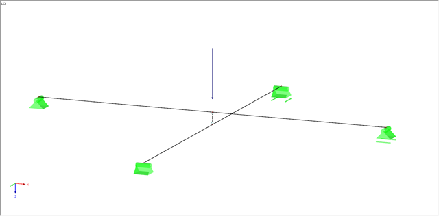
The response spectrum analysis is one of the most frequently used design methods in the case of earthquakes. This method has many advantages. The most important is the simplification: It simplifies the complexity of earthquakes so far that the design can be performed with reasonable effort. The disadvantage of this method is that a lot of information is lost due to this simplification. One way to moderate this disadvantage is to use the equivalent linear combination when combining the modal responses. This article explains this option by describing an example.

This article shows you how to create contacts between two or more parallel surfaces by controlling the transfer of forces between them.
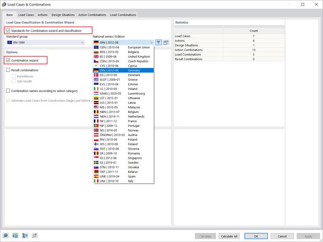
This article will show you how to use the Combination Wizard in RFEM 6 to reduce the number of load combinations to be analyzed, thus reducing the calculation effort and increasing the calculation efficiency.

In order to create a surface model with failing supports close to reality, an option called "Failure if contact perpendicular to surfaces failed" is available in RFEM 5 for contact solids under "Contact Parallel to Surfaces".

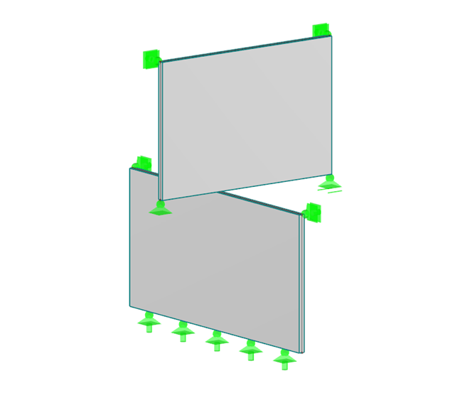
In RFEM, you can display the contact properties between two surfaces by means of contact solids. Among other things, you should ensure that both contact surfaces of a contact solid have the same integrated objects. Therefore, when modeling the contact surfaces, we recommend using the copy function in order to create the second contact surface.

In RFEM, you can display the contact properties between two surfaces by means of contact solids.

If nonlinear effects - such as failing supports, foundations, member nonlinearities, or contact solids - are used in the model, you can deactivate them in the global calculation parameters.

The response spectrum analysis is one of the most frequently used design methods in the case of earthquakes. This method has many advantages. The most important is the simplification: It simplifies the complexity of an earthquake to such an extent that an analysis can be carried out with reasonable effort. The disadvantage of this method is that a lot of information is lost due to this simplification. One way to mitigate this disadvantage is to use the equivalent linear combination when combining the modal responses. This article explains this option by describing an example.

This technical article deals with the stability analysis of a roof purlin, which is connected without stiffeners by means of a bolt connection on the lower flange to have a minimum manufacturing effort.
This article describes how to determine the contact force between two objects behaving like walls that are diagonally inclined at a certain angle on top of each other. Define a nodal release to determine this contact force. Since a nodal release requires certain conditions, this article shows two examples.
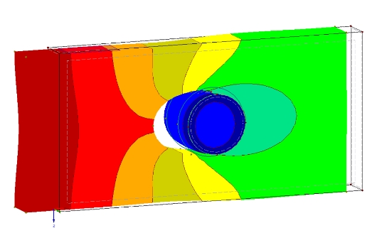
The definition of the non-linear contact problem plays an important role for more detailed investigations of shear/hole bearing connections or their immediate environment. This article uses a solid model to search for comparable and simplified surface models.
From time to time, two intersecting beams overlap at a short distance. Such a structure raises the question, with regard to the modeling, of how it is possible to consider a contact with force transmission under compression between the two beams, while the contact under tension (for example, in case of a lifting top beam) should fail.
![Structural System and Cross-Section Dimensions According to [1]](/en/webimage/009153/2417271/01-en-png.png?mw=640&hash=c76563b459152b19c98197ea6ba342be89d9a5bc)
There are several options for calculating a semi-rigid composite beam. They differ primarily in the type of modeling. Whereas the Gamma method ensures simple modeling, additional efforts are required when using other methods (for example, shear analogy) for the modeling which are, however, offset by the much more flexible application compared to the Gamma method.
.png?mw=640&hash=5852c5c8a1cdb9f021a168d75c0a0466fb430ef7)
Lattice towers represent typical applications in steel construction. Examples of this special type of truss structure are antenna and overhead line towers, as well as columns for wind power stations, cable cars, and supporting frame constructions. The modeling can be done individually in RFEM and RSTAB by entering various tower elements. Furthermore, you can use different copy functions and parameterized input options. However, this procedure normally requires considerable effort. It is more convenient to model such structures using prefabricated catalog elements provided by the Block Manager. These elements are automatically stored in the database during program installation. Thus, you can use tower segments, platforms, antenna brackets, cable ducts, and so on as parameterized building blocks for generating diverse tower structures.
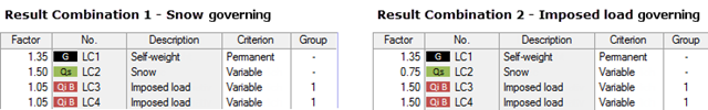
My previous article Result Combinations 1 explained the basic principles of result combinations on simple examples. This article describes a further application case that combines the definition options of Examples 1 and 2. Likewise, the effort should be compared to a combination by means of load combinations.
![Time-Dependent Settlement Components [2]](/en/webimage/009673/2419908/01-en-png-png.png?mw=640&hash=5e657e3feb5c1bb6d21727468dd85d91e1c9f29f)
For the serviceability limit state design according to Section 6.6 of Eurocode EN 1997‑1, settlement has to be calculated for spread foundations. RF-/FOUNDATION Pro allows you to perform the settlement calculation for a single foundation. For this, you can chose between an elastic and a solid foundation. By defining a soil profile, it is possible to consider several soil layers under the foundation base. The results of the settlement, foundation tilting, and vertical soil contact stress distribution are displayed graphically and in tables to provide a quick and clear overview of the calculation performed. In addition to the design of the foundation settlement in RF-/FOUNDATION Pro, the structural analysis determines the representative spring constants for the support and can be exported to the structural model of RFEM or RSTAB.
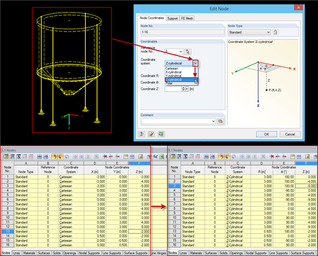
Rotation-symmetric structures or structural components are frequently entered in the Cartesian coordinate system. For example, subsequently changing the radius requires some effort, as the coordinates should be recalculated first and then updated for each node.
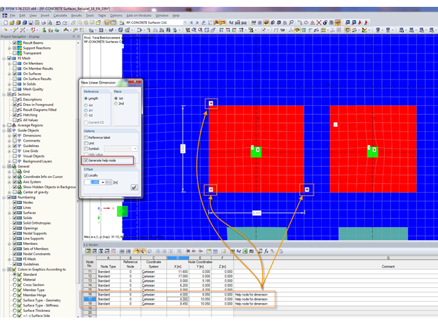
In order to set a dimension in RFEM, a physical node must exist at the locations to be dimensioned. Therefore, dimensioning free surface loads or graphical results was impossible without further effort until now.
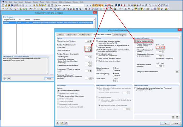
If nonlinearities are used in a model (for example, contact solids), an error message may appear at the end of the calculation due to the locally unfulfilled convergence criteria. The reason for this is that the convergence of the global iteration conditions governs in the calculation.
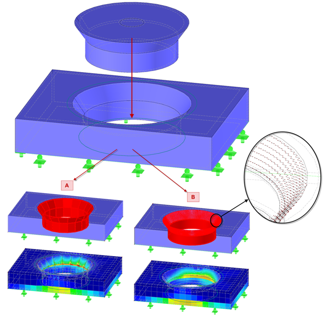
Contact solids can be created between two flat surfaces or between two cylindrical shells. However, if the area of the contact problem is a little more complicated, it is necessary either to simplify the system so that the requirements of a contact solid can be met, or to go back to the "old" modeling style using a rod model.
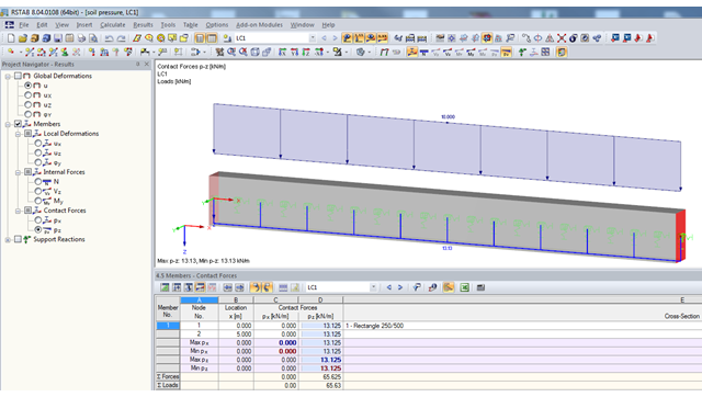
If a model should contain members with elastic foundations, the contact forces and moments are displayed in numerical form in the result windows. The graphical display of results is specified by the "Members" entry in the Results Navigator.
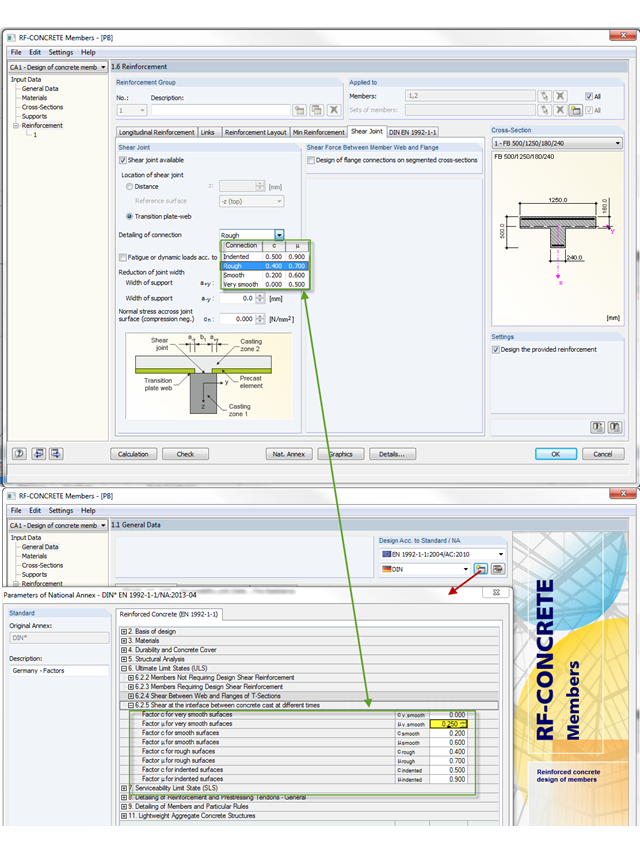
The shear resistance design value of a joint depends mainly on the formation or the roughness of the connection. When determining the ultimate limit state, this is considered by the factors µ (friction) and c (adhesion percentage of the contact area of the composite concrete).
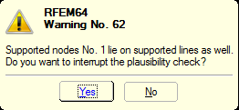
You can define nonlinear supports in RFEM and RSTAB. In RFEM, these are represented by nodal, line, and surface supports. Many customers contact us because of nonlinearities that are apparently not acting as desired. For example, there is a failing line support in a model. Since the structure is statically determined as supported, a linear nodal support is usually added. If the nodal support rests at the start or the end of a nonlinearly supported line, there is no clear definition of the degrees of freedom, so the nonlinearity cannot be considered properly. In this case, RFEM displays a warning message.